As a result we know that the scattering matrixof this four- port device has just 4 independentelements. HFC30-26 30kW HF Directional Coupler.

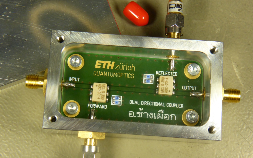
Figure 4 From Design And Development Of A Dual Directional Coupler With Transformers For Hf Band Applications Semantic Scholar
The directivity of the coupler depends on how well the isolated port is terminated.

. Excellent performance at the HF VHF and well into the UHF band. Another classic design a 20 dB directional coupler using two transformers in a configuration popularized by the Tandem Match wattmeter in QST and several editions of the ARRL Handbook. 1 - 1000 MHz.
RF HAMDESIGN is an engineering oriented organization specializing in the design and manufacture of high performance parabolic antennas computer controlled Antenna Rotators 3dB high power RF couplers RF High Power Antenna power splitters directional RF couplers and more items for RF transmission from HF through Microwave frequencies. 20 - 40 dB. 20 dB HF coupler Under construction.
Return loss at P1 P2. Design is critical to maintaining good performance in both directions. Return loss at P3.
This book presents a un ified approach to design using awide variety of active elements and resonator types - bipolar transistors FETs orMMICs with crystalL-CSAWcoaxial mcrosmp orother resonatorsStrong coverage of basicconcepts with many design CAD models and circuit examples. A directional coupler is a 4-port network that is designed to divide and distribute power. Two of the reasons for this difficulty are our desire for the device to be.
A broadband directional coupler based on ferrite cores is proposed for highfrequencyHFVeryhighfrequencyVHFUltraHighFrequency UHF communication systems. Very high frequency VHF is the ITU-designated range of radio frequency electromagnetic waves from 30 MHz to 300 MHz with corresponding wavelengths of one to ten meters. A 6 dB hybrid combiner from junkbox parts A homemade hybrid couplercombiner built several years ago and recently characterized.
Please excuse us while we update our home page and membership management systems. Coupling factor represents the primary property of a directional coupler To reduce 100 w to 100 mw Coupling factor -30 dB Directivityis the measure of how well a coupler isolates two opposite- travelling forward and reverse signals Creates region of uncertainty around all measurements Bird 43. These devices are used to unequally split the signal flowing in the mainline and to fully pass the signal flowing in the opposite direction.
Directional coupler topologies. This model provides 250W RF input power handling and passes. Both of these requirements were met by developing a theoretical model and were then validated by simulations in Agilents ADS.
A directional coupler separates signals based on the direction of signal propagation. Solutions Inc to redesign a 90-hybrid coupler with the center frequency of 19GHz. The sponsors requirements for the new design were to increase the bandwidth and decrease the device area.
Its schematic with the ports numbering used for the following graphs is shown below. The critical parameters for a directional coupler are. The maximum insertion loss at high frequencies is less than 08 dB.
This letter presents a miniature broadband directional coupler based on ferrite-core transformers. Directional Coupler Design The operational frequency of the directional coupler is specified to be 2712 MHz. 6950 In Stock Directional coupler HY1 1.
A classic 6 dB hybrid combiner design Wideband hybrid coupler similar to the classic ARRL Handbook design. 11 21 31 41 21 11 3141 31 11 2141 41 31 21 11. Circuit design and analysis.
Output samples of forwarding and reverse power flow are provided. 20 - 50 dB. Here transformer T 1 senses the main line current between the input and the load.
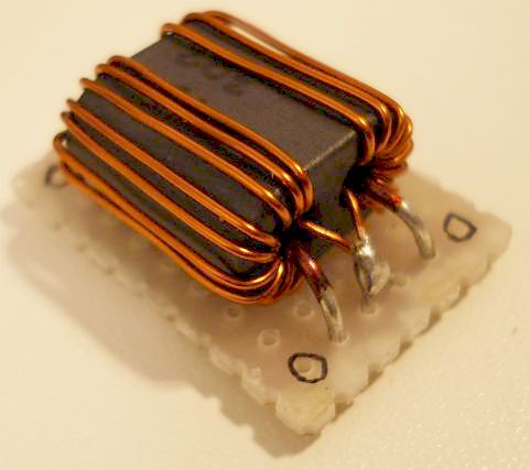
The transformer-type coupler is com- posed of two double-aperture ferrite cores and 1-mm-diameter strands. Mini-Circuits ZGBDC35-93HP is a coaxial bi-directional coupler with 35 dB nominal coupling across the 900 to 9000 MHz frequency range. The HFC1-30 is a wide band directional coupler for the HF frequency band.
8 - 38 dB. About Press Copyright Contact us Creators Advertise Developers Terms Privacy Policy Safety How YouTube works Test new features Press Copyright Contact us Creators. The forward coupling of the directional coupler is specified to be 24 dB.
Lossless Thus we require a. A directional coupler is used to sample the RF energy travelling in a transmission line useful for measuring power frequency and VSWR or impedance. Based on a resistive bridge design.
The coupler uses ferrite transformer techniques resulting in an extremely small compact device for permanent installation or for field measurement purposes. The ferrite cores with different relative permeabilities are screened to. This is a common operational frequency for plasma and MRI applications.
Order NP-1 6400 HF FilterDesign and Computer Simulation. If it is truly directional then it can separate the power flowing in opposite directions for instance forward power transmitted toward an antenna and reflected power returning from the antenna. Some Directional couplers Some Directional couplers.
In an ideal situation some portion of the signal flowing into port In will appear at Port Coupl. 6900 Add to cart More. Directivity 30 dB Forward 542012.
The impedance bridge of the N2PK VNA. Frequencies immediately below VHF are denoted high frequency HF and the next higher frequencies are known as ultra high frequency UHF. Wideband Component Design Directional Couplers In some systems it is necessary to have a continuous wideband directional coupler to provide a separate output that informs the user of how much power is in the main line and in which direction it is going.
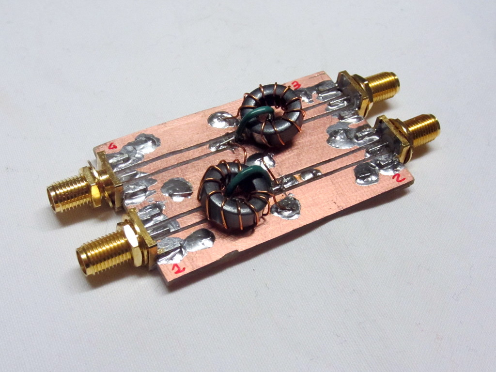
In Stock Add to Compare. This device can realise the coupling factor of 20 dB from 5 to 1000 MHz while keeping the voltage standing wave ratio VSWR of each port less than 12. The RF transformer-based topology uses two RF transformers Figure 2.
We will be debuting our new look on Wednesday so please join us then. The three most common topologies are RF transformer resistive bridged or coupled transmission lines. Analysis and Design of Coupled-Line Couplers A pair of coupled lines forms a 4-portdevice with twoplanes of reflection symmetryit exhibits D 4symmetry.
Directional coupler designs can be executed in several ways. Teflon is the specified substrate and is chosen because of its cost effectiveness. Although this would seem to be a particularly mundane and simple task these devices are both very important in microwave systems and very difficult to design and construct.
Diy Dual Directional Coupler An Add On To Our Scalar Network Analysers
2

K6jca More Notes On Directional Couplers For Hf The Bruene Coupler Part 2
20 Db Hf Coupler
Hf Directional Coupler By Sv3ora During The Construction Of A Signal Generator I Needed A Way To Keep It S Output Signal Amplitude Stable So I Needed An Alc Circuit This Involves Taking A Small Sample Of The Output Signal Rectifying It And Driving A Level

Rf Directional Couplers Circuit Design Raynet Repair Services
Figure 2 From Design And Development Of A Dual Directional Coupler With Transformers For Hf Band Applications Semantic Scholar
Hf Directional Coupler By Sv3ora During The Construction Of A Signal Generator I Needed A Way To Keep It S Output Signal Amplitude Stable So I Needed An Alc Circuit This Involves Taking A Small Sample Of The Output Signal Rectifying It And Driving A Level
0 comments
Post a Comment